Multi-inlet block
A front door for a chip. Between two and ten liquid inlets, each with its own membrane valve, combined by a branching tree down to a single outlet. The valves let you choose which inlet is open.
What it is for. Bringing several reagents onto one chip through one downstream channel, and selecting between them without any external valve manifold.
Variants
Sizes below are given in px: units of the design grid these parts were drawn on, where one unit is 0.0076 mm. That is not the printer's pixel. The printer has its own, different pixel size, and nothing on this page is expressed in it — see Hardware and process.
Showing one variant at a time. All of them are on this page.
inlet_block_10x_40_40_40_40_40_40_40_40_40_40_0
H.R.3.3 design

| Number of inlets | 10 |
|---|---|
| Valve diameter on each inlet | 40 px / 40 px / 40 px / 40 px / 40 px / 40 px / 40 px / 40 px / 40 px / 40 px |
| Membrane thickness | 1 layer |
| Fluid chamber height | 3 layers |
| Air chamber height | 6 layers |
| Channel cross-section | 8 px × 6 layers |
| Footprint | 630 × 1800 px |
| Ports | 10 fluid in, 1 fluid out, 10 air in, 10 air out |
| Layout grid | 0.0076 mm per px |
Files for this variant
inlet_block_2x_40_40_0
H.R.3.3 design
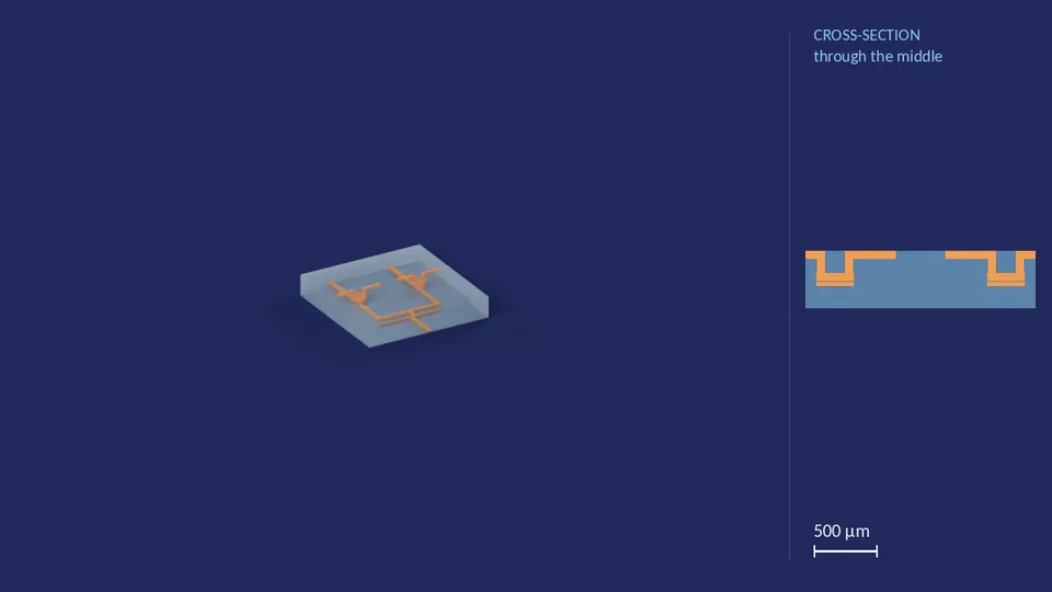
| Number of inlets | 2 |
|---|---|
| Valve diameter on each inlet | 40 px / 40 px |
| Membrane thickness | 1 layer |
| Fluid chamber height | 3 layers |
| Air chamber height | 6 layers |
| Channel cross-section | 8 px × 6 layers |
| Footprint | 360 × 360 px |
| Ports | 2 fluid in, 1 fluid out, 2 air in, 2 air out |
| Layout grid | 0.0076 mm per px |
Files for this variant
inlet_block_2x_40_80_0
H.R.3.3 design
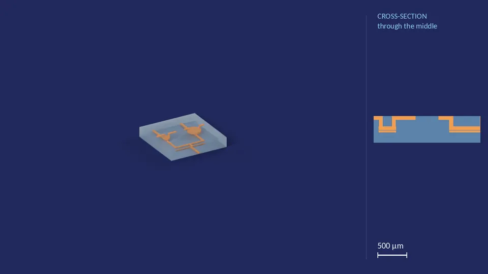
| Number of inlets | 2 |
|---|---|
| Valve diameter on each inlet | 40 px / 80 px |
| Membrane thickness | 1 layer |
| Fluid chamber height | 3 layers |
| Air chamber height | 6 layers |
| Channel cross-section | 8 px × 6 layers |
| Footprint | 360 × 360 px |
| Ports | 2 fluid in, 1 fluid out, 2 air in, 2 air out |
| Layout grid | 0.0076 mm per px |
Files for this variant
inlet_block_2x_80_80_0
H.R.3.3 design
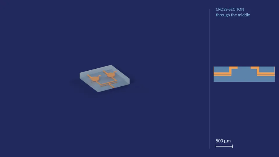
| Number of inlets | 2 |
|---|---|
| Valve diameter on each inlet | 80 px / 80 px |
| Membrane thickness | 1 layer |
| Fluid chamber height | 3 layers |
| Air chamber height | 6 layers |
| Channel cross-section | 8 px × 6 layers |
| Footprint | 360 × 360 px |
| Ports | 2 fluid in, 1 fluid out, 2 air in, 2 air out |
| Layout grid | 0.0076 mm per px |
Files for this variant
inlet_block_3x_40_40_40_0
H.R.3.3 design
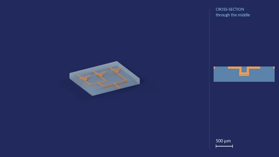
| Number of inlets | 3 |
|---|---|
| Valve diameter on each inlet | 40 px / 40 px / 40 px |
| Membrane thickness | 1 layer |
| Fluid chamber height | 3 layers |
| Air chamber height | 6 layers |
| Channel cross-section | 8 px × 6 layers |
| Footprint | 450 × 540 px |
| Ports | 3 fluid in, 1 fluid out, 3 air in, 3 air out |
| Layout grid | 0.0076 mm per px |
Files for this variant
inlet_block_3x_40_40_80_0
H.R.3.3 design
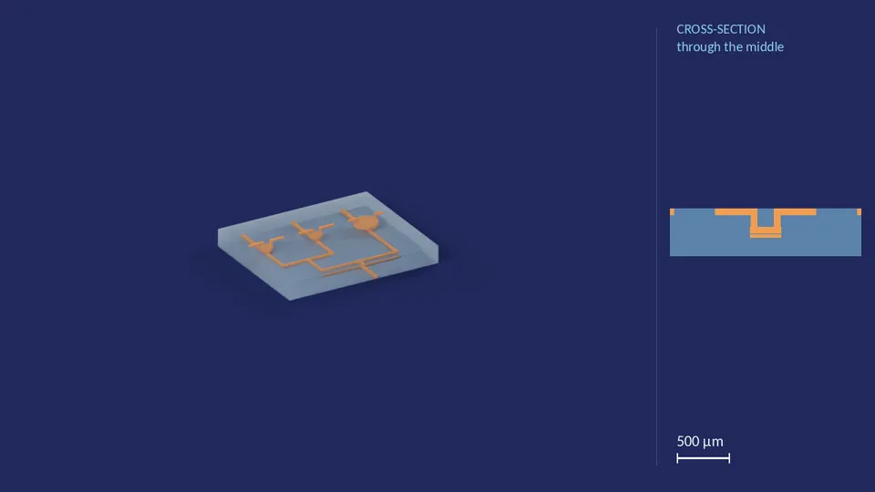
| Number of inlets | 3 |
|---|---|
| Valve diameter on each inlet | 40 px / 40 px / 80 px |
| Membrane thickness | 1 layer |
| Fluid chamber height | 3 layers |
| Air chamber height | 6 layers |
| Channel cross-section | 8 px × 6 layers |
| Footprint | 450 × 540 px |
| Ports | 3 fluid in, 1 fluid out, 3 air in, 3 air out |
| Layout grid | 0.0076 mm per px |
Files for this variant
inlet_block_3x_80_60_40_0
H.R.3.3 design
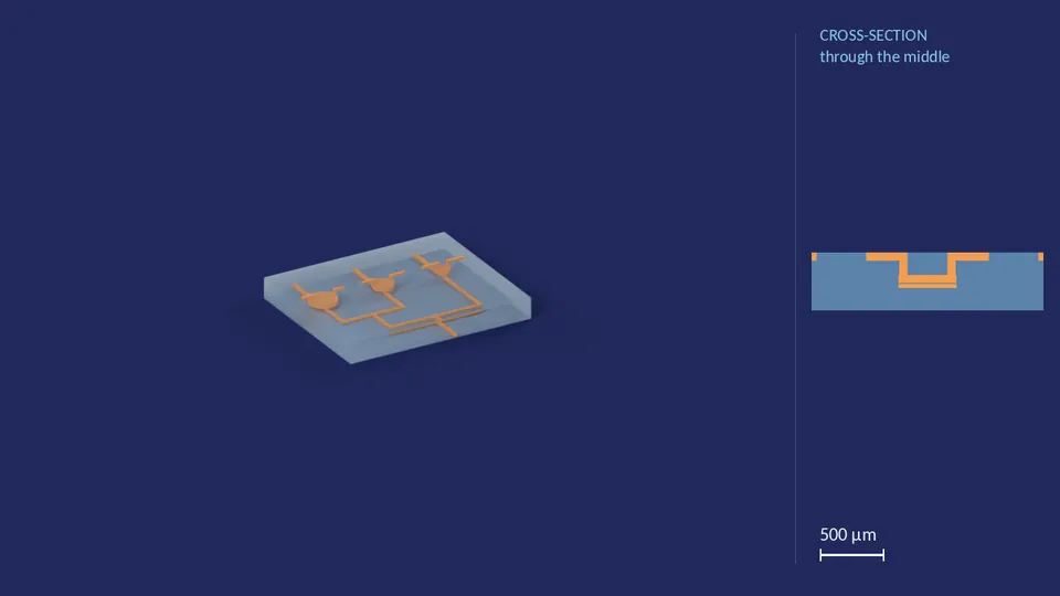
| Number of inlets | 3 |
|---|---|
| Valve diameter on each inlet | 80 px / 60 px / 40 px |
| Membrane thickness | 1 layer |
| Fluid chamber height | 3 layers |
| Air chamber height | 6 layers |
| Channel cross-section | 8 px × 6 layers |
| Footprint | 450 × 540 px |
| Ports | 3 fluid in, 1 fluid out, 3 air in, 3 air out |
| Layout grid | 0.0076 mm per px |
Files for this variant
inlet_block_3x_80_80_80_0
H.R.3.3 design
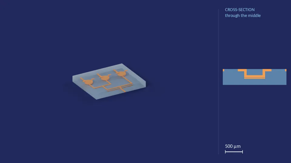
| Number of inlets | 3 |
|---|---|
| Valve diameter on each inlet | 80 px / 80 px / 80 px |
| Membrane thickness | 1 layer |
| Fluid chamber height | 3 layers |
| Air chamber height | 6 layers |
| Channel cross-section | 8 px × 6 layers |
| Footprint | 450 × 540 px |
| Ports | 3 fluid in, 1 fluid out, 3 air in, 3 air out |
| Layout grid | 0.0076 mm per px |
Files for this variant
inlet_block_4x_150_150_150_150_0
H.R.3.3 design
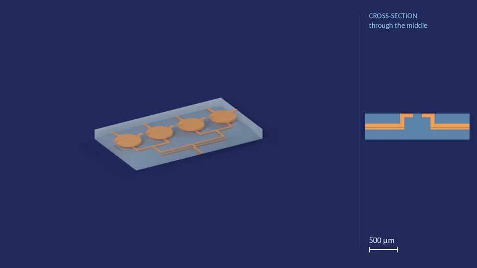
| Number of inlets | 4 |
|---|---|
| Valve diameter on each inlet | 150 px / 150 px / 150 px / 150 px |
| Membrane thickness | 1 layer |
| Fluid chamber height | 3 layers |
| Air chamber height | 6 layers |
| Channel cross-section | 8 px × 6 layers |
| Footprint | 480 × 840 px |
| Ports | 4 fluid in, 1 fluid out, 4 air in, 4 air out |
| Layout grid | 0.0076 mm per px |
Files for this variant
inlet_block_4x_190_190_190_190_0
H.R.3.3 design
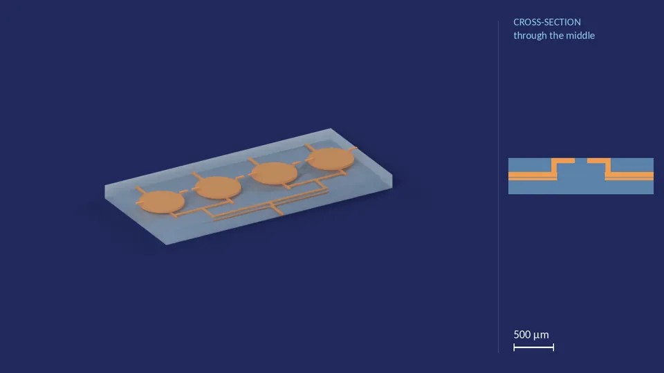
| Number of inlets | 4 |
|---|---|
| Valve diameter on each inlet | 190 px / 190 px / 190 px / 190 px |
| Membrane thickness | 1 layer |
| Fluid chamber height | 3 layers |
| Air chamber height | 6 layers |
| Channel cross-section | 8 px × 6 layers |
| Footprint | 510 × 1080 px |
| Ports | 4 fluid in, 1 fluid out, 4 air in, 4 air out |
| Layout grid | 0.0076 mm per px |
Files for this variant
inlet_block_4x_40_40_40_40_0
H.R.3.3 design
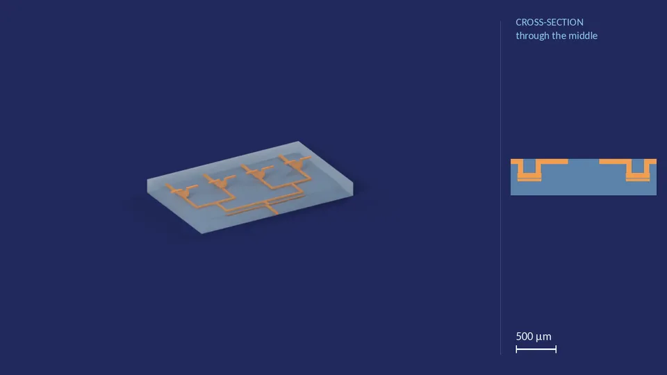
| Number of inlets | 4 |
|---|---|
| Valve diameter on each inlet | 40 px / 40 px / 40 px / 40 px |
| Membrane thickness | 1 layer |
| Fluid chamber height | 3 layers |
| Air chamber height | 6 layers |
| Channel cross-section | 8 px × 6 layers |
| Footprint | 450 × 720 px |
| Ports | 4 fluid in, 1 fluid out, 4 air in, 4 air out |
| Layout grid | 0.0076 mm per px |
Files for this variant
inlet_block_4x_40_40_80_80_0
H.R.3.3 design
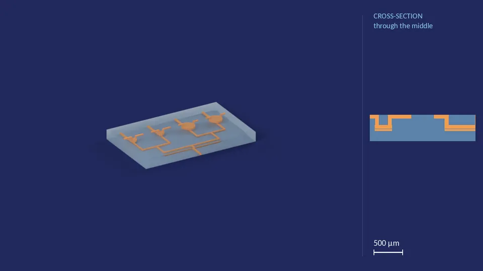
| Number of inlets | 4 |
|---|---|
| Valve diameter on each inlet | 40 px / 40 px / 80 px / 80 px |
| Membrane thickness | 1 layer |
| Fluid chamber height | 3 layers |
| Air chamber height | 6 layers |
| Channel cross-section | 8 px × 6 layers |
| Footprint | 450 × 720 px |
| Ports | 4 fluid in, 1 fluid out, 4 air in, 4 air out |
| Layout grid | 0.0076 mm per px |
Files for this variant
inlet_block_4x_40_80_40_80_0
H.R.3.3 design
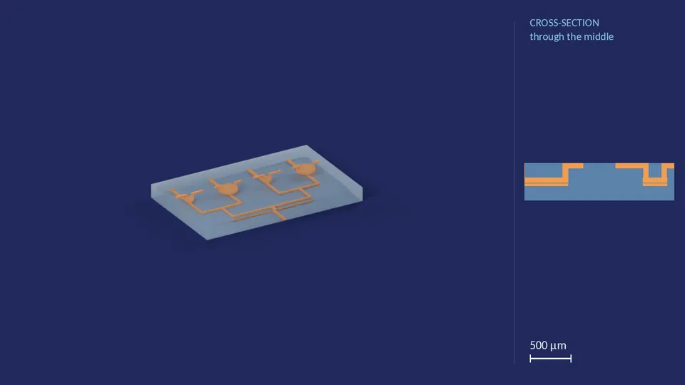
| Number of inlets | 4 |
|---|---|
| Valve diameter on each inlet | 40 px / 80 px / 40 px / 80 px |
| Membrane thickness | 1 layer |
| Fluid chamber height | 3 layers |
| Air chamber height | 6 layers |
| Channel cross-section | 8 px × 6 layers |
| Footprint | 450 × 720 px |
| Ports | 4 fluid in, 1 fluid out, 4 air in, 4 air out |
| Layout grid | 0.0076 mm per px |
Files for this variant
inlet_block_5x_190_190_190_190_190_0
H.R.3.3 design
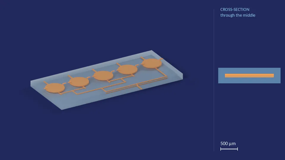
| Number of inlets | 5 |
|---|---|
| Valve diameter on each inlet | 190 px / 190 px / 190 px / 190 px / 190 px |
| Membrane thickness | 1 layer |
| Fluid chamber height | 3 layers |
| Air chamber height | 6 layers |
| Channel cross-section | 8 px × 6 layers |
| Footprint | 600 × 1350 px |
| Ports | 5 fluid in, 1 fluid out, 5 air in, 5 air out |
| Layout grid | 0.0076 mm per px |
Files for this variant
inlet_block_5x_40_40_40_40_40_0
H.R.3.3 design
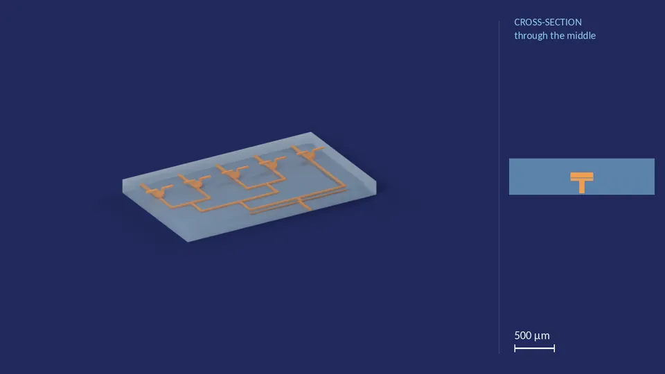
| Number of inlets | 5 |
|---|---|
| Valve diameter on each inlet | 40 px / 40 px / 40 px / 40 px / 40 px |
| Membrane thickness | 1 layer |
| Fluid chamber height | 3 layers |
| Air chamber height | 6 layers |
| Channel cross-section | 8 px × 6 layers |
| Footprint | 540 × 900 px |
| Ports | 5 fluid in, 1 fluid out, 5 air in, 5 air out |
| Layout grid | 0.0076 mm per px |
Files for this variant
inlet_block_5x_40_40_80_40_40_0
H.R.3.3 design
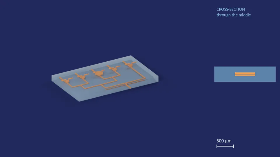
| Number of inlets | 5 |
|---|---|
| Valve diameter on each inlet | 40 px / 40 px / 80 px / 40 px / 40 px |
| Membrane thickness | 1 layer |
| Fluid chamber height | 3 layers |
| Air chamber height | 6 layers |
| Channel cross-section | 8 px × 6 layers |
| Footprint | 540 × 900 px |
| Ports | 5 fluid in, 1 fluid out, 5 air in, 5 air out |
| Layout grid | 0.0076 mm per px |
Files for this variant
inlet_block_5x_40_40_80_40_60_0
H.R.3.3 design
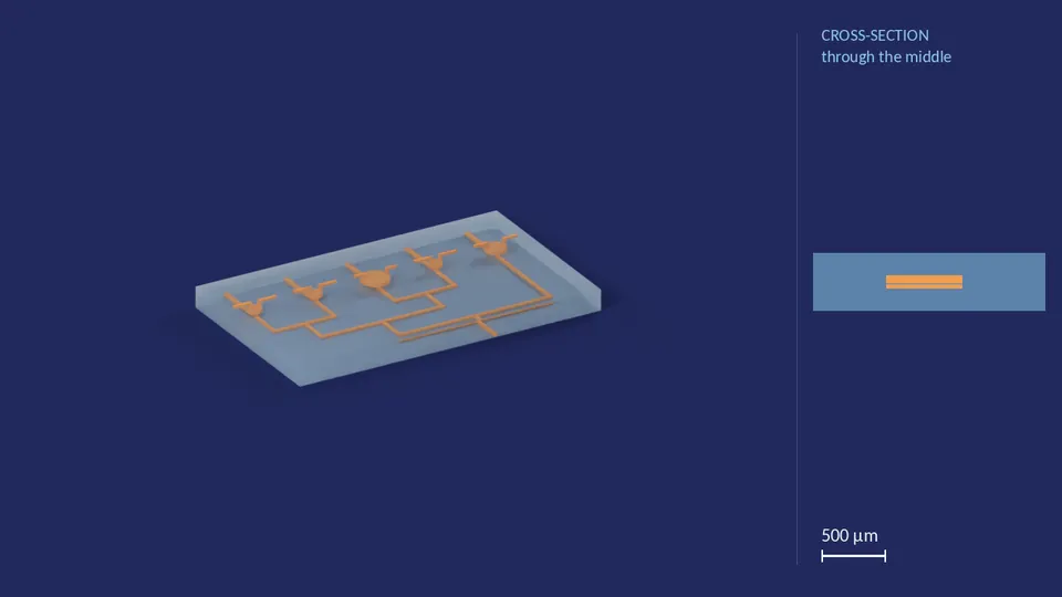
| Number of inlets | 5 |
|---|---|
| Valve diameter on each inlet | 40 px / 40 px / 80 px / 40 px / 60 px |
| Membrane thickness | 1 layer |
| Fluid chamber height | 3 layers |
| Air chamber height | 6 layers |
| Channel cross-section | 8 px × 6 layers |
| Footprint | 540 × 900 px |
| Ports | 5 fluid in, 1 fluid out, 5 air in, 5 air out |
| Layout grid | 0.0076 mm per px |
Files for this variant
inlet_block_6x_150_150_150_150_150_150_0
H.R.3.3 design
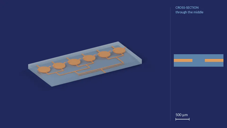
| Number of inlets | 6 |
|---|---|
| Valve diameter on each inlet | 150 px / 150 px / 150 px / 150 px / 150 px / 150 px |
| Membrane thickness | 1 layer |
| Fluid chamber height | 3 layers |
| Air chamber height | 6 layers |
| Channel cross-section | 8 px × 6 layers |
| Footprint | 570 × 1260 px |
| Ports | 6 fluid in, 1 fluid out, 6 air in, 6 air out |
| Layout grid | 0.0076 mm per px |
Files for this variant
inlet_block_6x_40_40_40_40_40_40_0
H.R.3.3 design
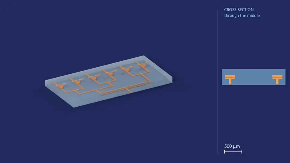
| Number of inlets | 6 |
|---|---|
| Valve diameter on each inlet | 40 px / 40 px / 40 px / 40 px / 40 px / 40 px |
| Membrane thickness | 1 layer |
| Fluid chamber height | 3 layers |
| Air chamber height | 6 layers |
| Channel cross-section | 8 px × 6 layers |
| Footprint | 540 × 1080 px |
| Ports | 6 fluid in, 1 fluid out, 6 air in, 6 air out |
| Layout grid | 0.0076 mm per px |
Files for this variant
inlet_block_8x_40_40_40_40_40_40_40_40_0
H.R.3.3 design

| Number of inlets | 8 |
|---|---|
| Valve diameter on each inlet | 40 px / 40 px / 40 px / 40 px / 40 px / 40 px / 40 px / 40 px |
| Membrane thickness | 1 layer |
| Fluid chamber height | 3 layers |
| Air chamber height | 6 layers |
| Channel cross-section | 8 px × 6 layers |
| Footprint | 540 × 1440 px |
| Ports | 8 fluid in, 1 fluid out, 8 air in, 8 air out |
| Layout grid | 0.0076 mm per px |