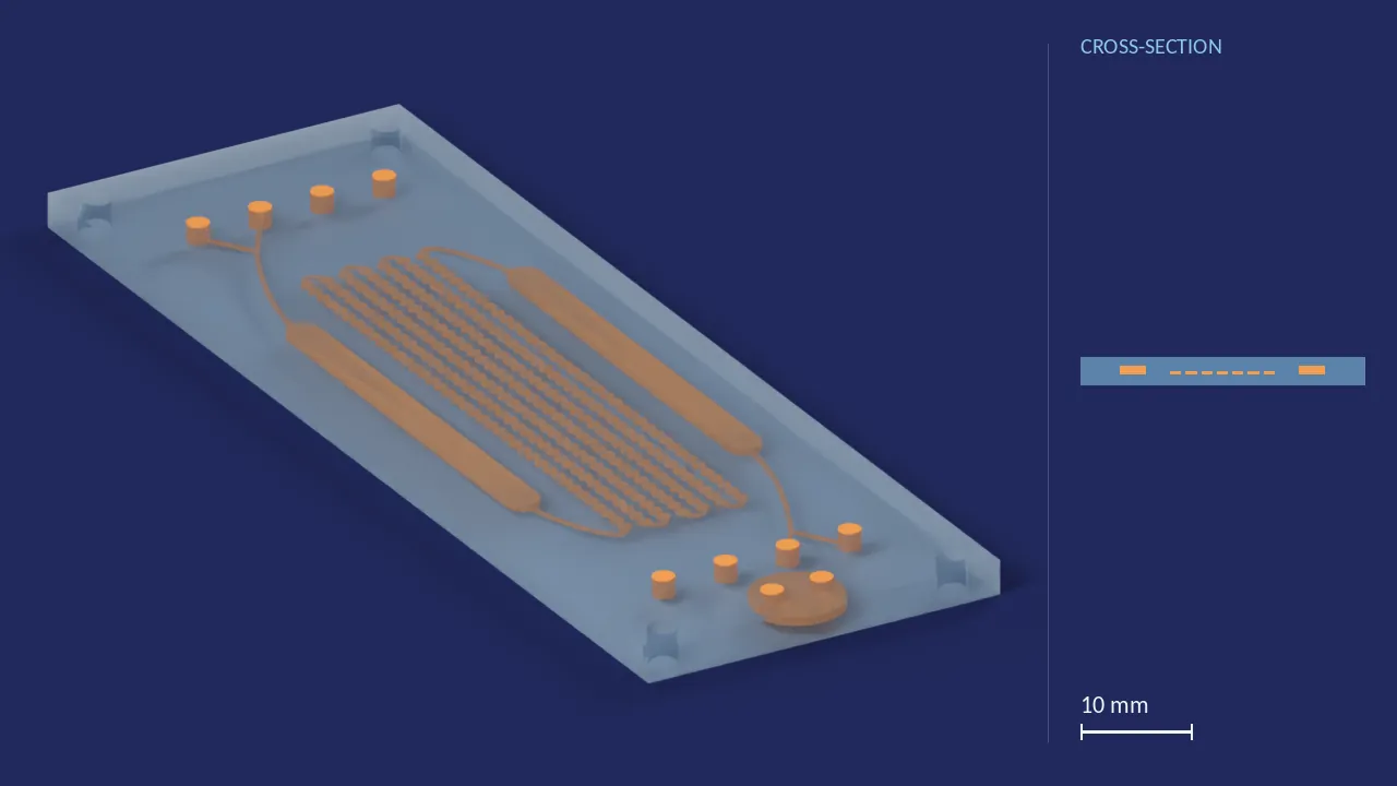
Internal geometry — X-ray
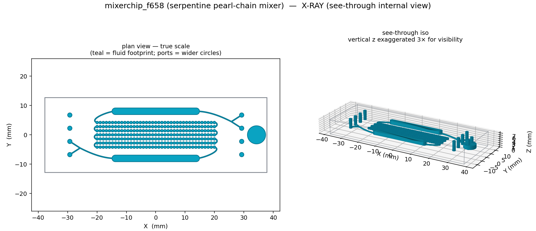
See-through internal view. Left: fluid footprint in plan, true scale (teal); ports show as the wider circles. Right: isometric of the internal void, vertical z exaggerated 3× for visibility. The exterior is an opaque solid block — this is what is inside it.
Download: PNG (x-ray)
Longitudinal section & exterior
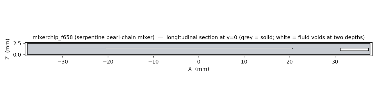
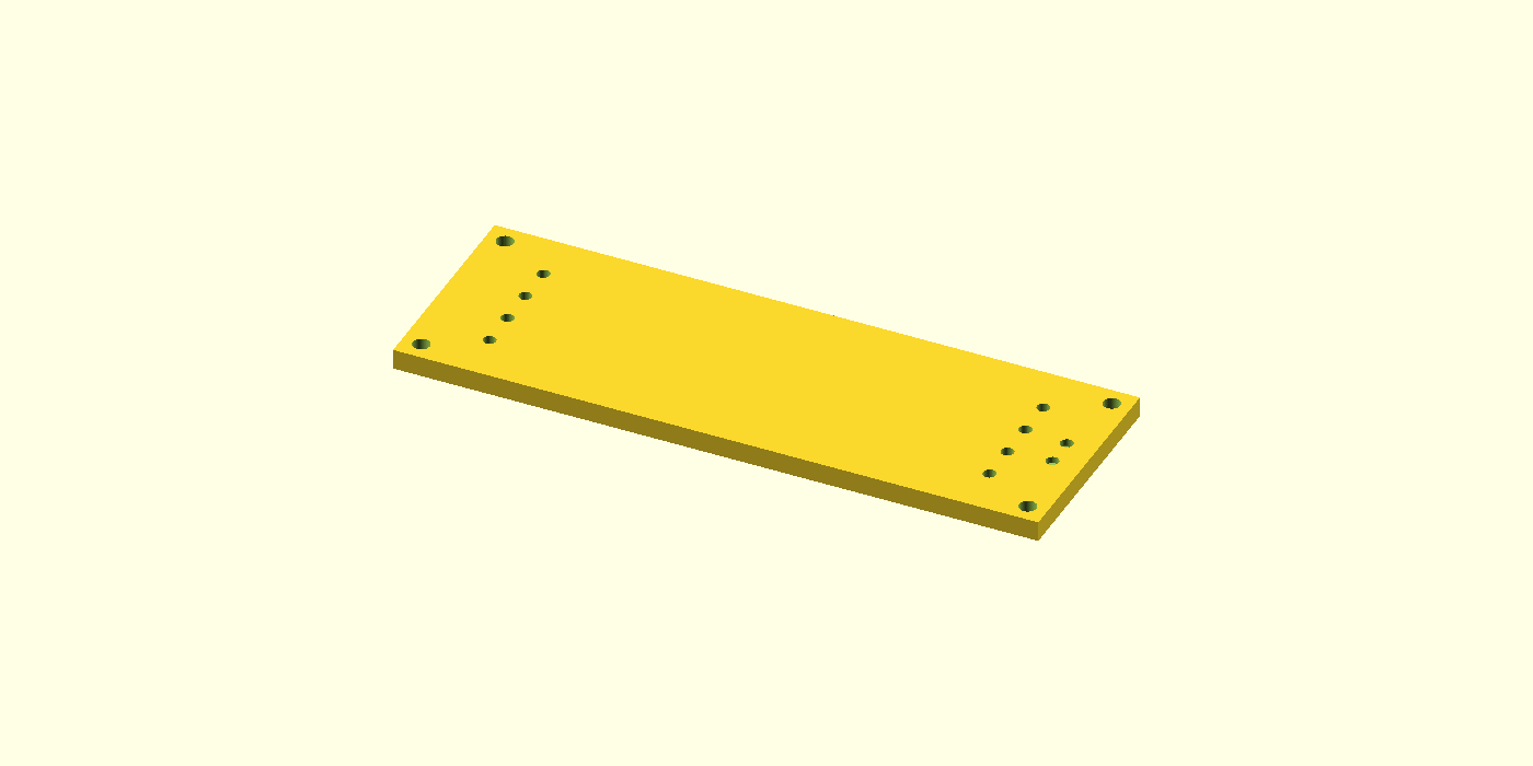
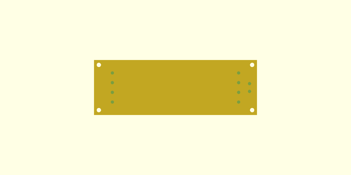
Longitudinal section at y=0 (left): grey = solid, white = fluid voids. Exterior isometric (right): the outside of the CAD model, drawn opaque. Click either for full resolution.
Download: PNG (section) · PNG (top) · PNG (iso)
Description
A monolithic resin-SLA design of a pearl-chain mixer, drawn from measurements of the Fluidic 658 technical datasheet. Two inlet ports, joined by a Y-junction, feed a viewing stadium; a 7-pass pearl-chain serpentine (Ø0.9 mm pearls on 0.3 mm necks) mixes; a second viewing stadium shows the result; two outlet ports, joined by a second Y-junction, drain it. The other four ports are bare holes that connect to nothing, as on the datasheet. A round chamber at one end is an empty open well that nothing flows through. Channels are 0.20 mm deep; the stadiums and the round chamber 0.60 mm.
Round chamber: an empty open well copying an unlabelled circle on the datasheet drawing. Nothing flows through it: it is a separate cavity with two 1.5 mm holes of its own to the top face, so uncured resin can drain. Its wall to the end face is only 0.34 mm.
Ports
Seen from the top with the round chamber at the right-hand end, as in the plan view above. Positions are in mm from the chip’s centre, x along its length toward the round chamber. Every hole is a straight Ø1.5 mm bore from the top face.
| port | where | connects to |
|---|---|---|
| Inlets (2) | the upper two at the right-hand end: (+29.25, +6.75) and (+29.25, +2.25) | a Y-junction, then the first viewing stadium |
| Outlets (2) | the lower two at the left-hand end: (−29.25, −6.75) and (−29.25, −2.25) | a Y-junction, from the second viewing stadium |
| Bare holes (4) | the upper two at the left-hand end and the lower two at the right-hand end: (−29.25, +2.25), (−29.25, +6.75), (+29.25, −6.75), (+29.25, −2.25) | nothing, as on the datasheet. Do not push tubing into them. |
| Round-chamber holes (2) | beside the right-hand ports: (+34.30, +1.80) and (+34.30, −1.80) | the round chamber only |
The four bare holes are blind: they stop 0.10 mm below the channel floor and touch no channel. Seen from outside the model, they look like the working ports.
Verification
| metric | value |
|---|---|
| Serpentine passes | 7, counted on the mesh; 39 pearls each, on a 1.05 mm pitch |
| Pearl Ø / neck | 0.90 / 0.30 mm (datasheet: 0.9 / 0.3) |
| Channel / chamber depth | 0.20 / 0.60 mm (datasheet: 0.2 / 0.6) |
| Connector channels (W × H) | 0.30 × 0.20 mm (the datasheet drawing shows 0.5 × 0.2) |
| Viewing stadiums (each) | 39.99 µl (datasheet: ca. 40) |
| Serpentine (7 passes + U-turns) | 37.94 µl (datasheet: ca. 35; +8.4%) |
| Round chamber | Ø6.22 × 0.60 mm, 18.18 µl; nothing flows through it |
| Mixer network, inlets to outlets, with its 4 port holes | 131.57 µl inside the block |
| Void | watertight, 6 bodies: the mixer network, the round chamber, and 4 bare holes |
| Chip watertight | True |
| Chip Euler number | −14 (genus 8: 4 mounting holes, 3 from the mixer’s 4 open ports, 1 from the chamber’s 2 holes; the bare holes are blind) |
| Round chamber’s wall to the end face | 0.34 mm |
| Footprint (L × W × H) | 75.5 × 25.5 × 2.4 mm |
| Min feature vs Phrozen 12K X (px_min = 200/19) | 10.53 px |
| Min feature vs Phrozen 12K Y (px_min = 200/24) | 8.33 px |
Every figure here is measured from the files offered below: the chip and void STLs, and fresh renders of the .scad for the serpentine, stadium and chamber volumes. Mesh checks use trimesh with merged vertices. The bundled README repeats them.
Source & print adaptation
Source dimensions are what the originating design publishes; ours are what our CAD model is drawn at. Where the two are the same number, no feature was resized to print. No public URL for the source is on record in this repository, so it is cited as plain text rather than linked.
Provenance & caveats
From the datasheet (measured off the Fluidic 658 drawing): channel depth 0.20 mm and stadium depth 0.60 mm, pearl Ø0.9 mm on 0.3 mm necks, 7 passes, the 8-port grid and which four ports the channels reach, the two stadiums (ca. 40 µl each), the serpentine (ca. 35 µl) and the 75.5 × 25.5 mm outline. Ours, not from the datasheet: the connector channels are 0.30 mm wide where the drawing shows 0.5 mm; the exact curves of the connectors; the round chamber’s depth and its two holes; the 2.4 mm block and its four mounting holes. Serpentine: it holds 37.9 µl against the datasheet’s ca. 35 µl (+8.4%). Bare holes: four of the eight ports connect to nothing, as on the datasheet — do not push tubing into them (see Ports). Round chamber: an empty open well copying an unlabelled circle on the datasheet; nothing flows through it; its wall to the end face is only 0.34 mm. The .scad’s original header is older than its geometry. A dated correction note at the top of the file lists what it gets wrong — one outlet, the unused ports joined to the stadiums, and a pixel pitch for the lab’s printer that the header now corrects — and says the code builds what this page describes. Ports are straight bores, standing in for the vendor’s MFCS Mini Luer sockets. Status — Phrozen Sonic Mighty 12K design, checked in CAD: the geometry is watertight and volumetrically checked in CAD — see the Verification table above for the numbers.
Files to download
- SCAD
mixerchip_f658.scad15.4 KBDownload - STL
mixerchip_f658.stl8.1 MBDownload - STL
void_mixerchip_f658.stl8.0 MBDownloadFor inspection, not for printing: the fluid network, every space that holds liquid, as a solid. - PNG
mixerchip_f658_xray.png235.6 KBDownload - PNG
mixerchip_f658_section.png24.8 KBDownload - MD
README.md4.3 KBDownload