Process limits live in one place. These tools check geometry, not printability. Everything each one lists as not checked — minimum feature size, wall survivability, unsupported span, resin clearing — is recorded on Hardware and process, together with the printers and resin the designs are made on and a provenance label on every figure.

Each picture is a computer render of a design, not a photograph of a print. Each shows an example: its settings are listed under it, and a link opens the maker set up the same way. The block is drawn see-through so the channels show, and each picture is scaled to fit its frame, so the three are not to the same scale.

Straight Channel Maker
Free · works in your browser

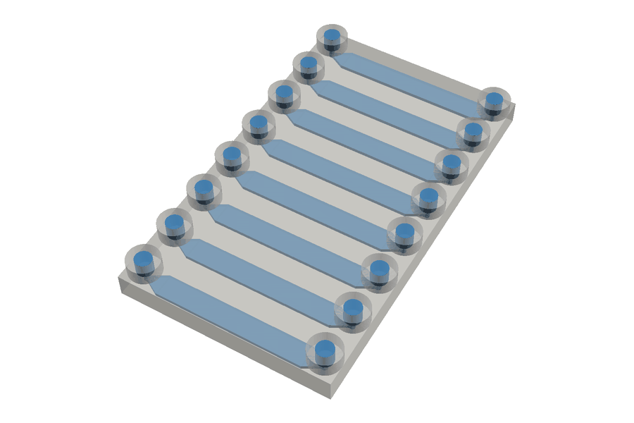
Computer render of a design, not a print: eight straight blue channels side by side in a see-through block, each tapering at both ends to a round port, with a raised round socket standing on the top face over every port: sixteen sockets, in two rows of eight.

A design, not a print: what the channel maker makes with the settings below. The block and its raised sockets are drawn see-through; everything hollow inside them, the channels, ports and sockets, is blue.

Printer
19 µm pixels, 10 µm layers
Channel
8 channels side by side, 4.503 mm (237 px) apart centre to centre; each 2.109 mm (111 px) wide, 350 µm (35 layers) high and 17.993 mm (947 px) long
Surrounding solid
side walls 741 µm (39 px); floor and roof each 1 mm (100 layers)
Ports
vertical ports through the roof, 494 µm (26 px) across, each channel end tapered (60°); tube into a raised socket, for 1/16 in (1.59 mm) tubing, 1.5 mm (150 layers) deep, with a 741 µm (39 px) boss wall

Start from this example →

What it is. A straight channel for liquid to flow through, inside a small solid block. It is the simplest part there is.

What is inside it. One channel, or several side by side, running along the block, each with an opening at each end: by default, a round port up through the top of the block. You set the width, height and length on your printer’s grid.

What you would use it for. Carrying liquid from one place to another, or holding a flow back: a longer or narrower channel resists flow more, and the maker shows by how much as you change it.

A design for the grid you choose: the BYU printer’s, the Phrozen Sonic Mighty 12K’s or your own.

What we check, and what we don't: We check the shape can actually be built, and stop you if it cannot. We do not check whether your printer can make it this small, whether a thin wall survives handling, or whether liquid resin drains out of a long channel. Nobody has tested those limits, so we do not invent one.

Technical details

Available · Runs in your browser

Build a printable straight rectangular channel from pixel-grid parameters, with the hydraulic resistance, pressure drop and flow rate as you type.

Enter the channel on your printer's grid — width and length in pixels, height in layers — choose round ports through the roof (the default), square ones, ports for tubing (into the chip, into a raised socket or over a post), or open ends, and read the cross-section, internal volume, hydraulic resistance, pressure/flow and Reynolds number live. Type a real-world µm value into any field and it snaps to the nearest whole pixel and tells you what it snapped to.

Downloads parametric OpenSCAD (standalone, no includes), a watertight binary STL built directly in the browser, and a JSON record of every parameter and computed value. Nothing is uploaded and there is no backend.

What we check, and what we don't: blocking checks cover geometric self-consistency, and the one documented process rule (h < w, from the h.r.3.3 PDK's rectangular-channel component document) is shown pass/fail. Minimum feature size, wall survivability and resin clearing have no limit in the design kit's documentation, so the tool lists them as not checked rather than inventing a threshold. On the BYU grid it also compares the block with the image BYU publishes for the OS1, 2560 × 1600 pixels (19.5 × 12.2 mm, BYU’s rounded figure), in pixels and either way round, and flags a block bigger both ways without refusing the files (the OS1). Where those limits are recorded — and where they are not — is on Hardware and process.
Chamber Chip Maker

Free · works in your browser

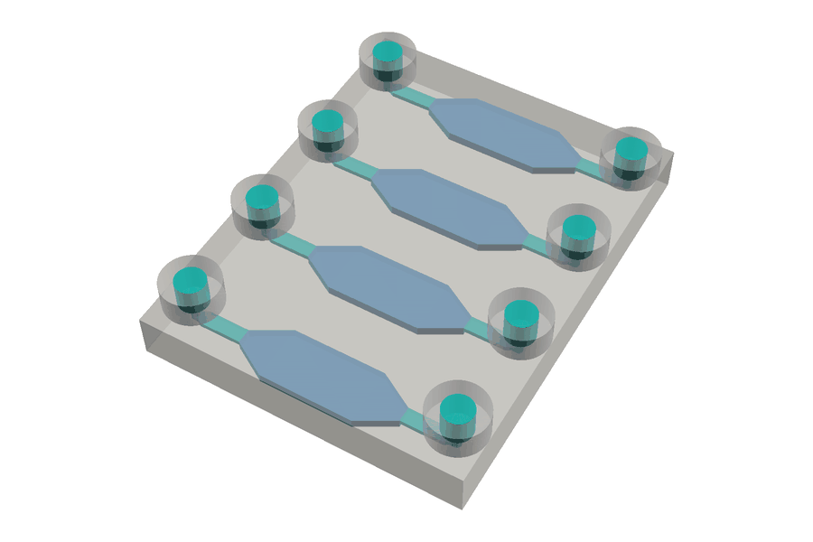
Computer render of a design, not a print: four separate paths side by side in a see-through block. On each, a short green channel leads from a raised round socket on the top face into a long six-sided blue chamber, which tapers at both ends to the channel's width, and a second channel leads on to another raised socket: eight sockets, in two rows of four.

A design, not a print: what the chamber maker makes with the settings below. The block and its raised sockets are drawn see-through; the chambers are blue, and the channels, ports and sockets green.

Printer
19 µm pixels, 10 µm layers
Layout
parallel: 4 chambers, each on its own path, 6.004 mm (316 px) apart centre to centre
Chambers
3.002 mm (158 px) wide, flat for 4.997 mm (263 px) with a 1.9 mm (100 px) taper at each end, 500 µm (50 layers) deep; channels roof-aligned
Channels
798 µm (42 px) wide and 250 µm (25 layers) high; inlet 3.002 mm (158 px) and outlet 3.002 mm (158 px) long
Surrounding solid
side walls 741 µm (39 px); floor and roof each 1 mm (100 layers)
Ports
vertical ports through the roof, 494 µm (26 px) across, each channel end tapered (60°); tube into a raised socket, for 1/16 in (1.59 mm) tubing, 1.5 mm (150 layers) deep, with a 741 µm (39 px) boss wall

Start from this example →

What it is. A chip with small wells, called chambers, joined by channels.

What is inside it. Up to eight six-sided chambers, either in a row on one path or on separate paths side by side, with a channel into and out of each. Type the volume you want in each chamber and the maker works out its size.

What you would use it for. Holding a known amount of liquid in one place. The maker shows each chamber’s volume, and how long liquid takes to fill a chamber and to pass through it at the flow you set.

A design for the grid you choose: the BYU printer’s, the Phrozen Sonic Mighty 12K’s or your own.

What we check, and what we don't: We check the shape can actually be built, and stop you if it cannot. We do not check whether the roof over a wide well will sag, whether your printer can make these features, or whether liquid resin drains out. Nobody has tested those limits, so we do not invent one.

Technical details

Available · Runs in your browser

Build a chamber chip with up to eight tapered hexagonal chambers — in series on one path, or as N independent parallel paths — and solve the chamber size from a target volume in µL.

Chambers are hexagonal in plan: the channel opens out over a taper, runs flat at the chamber width, and closes back down over a second taper. Choose one serial path or N independent parallel paths, enter everything on your printer's grid, pick whether the channel meets the chamber roof, floor or centre, and read the per-chamber and total volumes, the dead-volume fraction, the laminar pressure drop and flow rate, residence and fill times, and the diffusion time across the chamber depth as you type.

The volume solver works both ways: change the geometry and the volume follows, or type a target volume and it solves the chamber's flat length on the pixel grid and reports exactly what the grid delivers and how far that lands from the target — and refuses, rather than clamping, when the target is smaller than the tapers alone can hold. Downloads parametric OpenSCAD, a watertight binary STL built in the browser, and a JSON record of every parameter and computed value.

What we check, and what we don't: blocking checks cover geometric self-consistency and the connectivity the chosen layout claims; the one documented process rule (h < w on the channel, from the h.r.3.3 PDK) is shown pass/fail. The unsupported chamber roof span is displayed prominently but not gated — the design kit gives no span limit to gate it against. Ceiling sag, whether a taper is long enough to avoid trapping air, how far the printed taper departs from the true trapezoid once the slicer stair-steps it, wall survivability and resin clearing are listed as not checked. Ports are plain geometric primitives, not h.r.3.3 library interfaces: generated chips do not natively mate with Foundry component library parts. On the BYU grid it also compares the block with the image BYU publishes for the OS1, 2560 × 1600 pixels (19.5 × 12.2 mm, BYU’s rounded figure), in pixels and either way round, and flags a block bigger both ways without refusing the files (the OS1). Where those limits are recorded — and where they are not — is on Hardware and process.

Droplet Generator Maker

Free · works in your browser

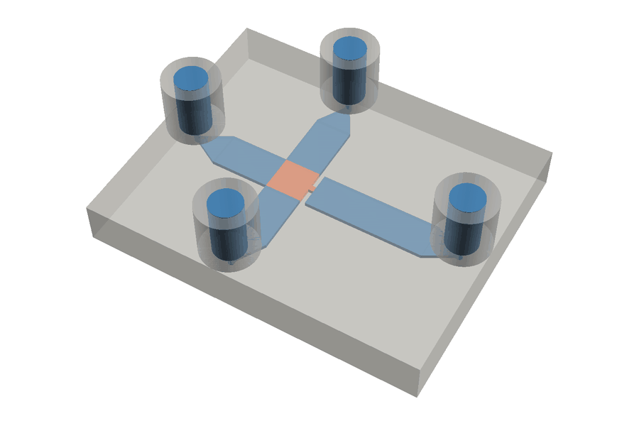
Computer render of a design, not a print: a flat see-through block holding a flow-focusing cross. Four blue channels meet at an orange square; the longest, the outlet, leaves it through a short orange neck, the nozzle. Each channel's far end tapers to a round port under a raised round socket standing on the top face: four sockets.

A design, not a print: what the droplet maker makes with the settings below. The block and its raised sockets are drawn see-through; the junction box and its nozzle are orange, and the channels, ports and sockets blue.

Printer
7.6 µm pixels, 10 µm layers
Junction
flow focusing (single cross), every channel 100 µm (10 layers) deep
Geometry
a junction box 912 µm (120 px) square; the dispersed inlet 912 µm (120 px) wide and 2.28 mm (300 px) long, and each continuous inlet 912 µm (120 px) wide and 2.28 mm (300 px) long; the orifice, the nozzle, 136.8 µm (18 px) wide and 136.8 µm (18 px) long; the outlet 912 µm (120 px) wide and 3.8 mm (500 px) long
Surrounding solid
side walls 304 µm (40 px); floor and roof each 500 µm (50 layers)
Ports
vertical ports through the roof, 152 µm (20 px) across, each channel end tapered (60°); tube into a raised socket, for 1/32 in (0.79 mm) tubing, 1.5 mm (150 layers) deep, with a 304 µm (40 px) boss wall

Start from this example →

What it is. The junction where two liquids that do not mix meet, so that one breaks up into droplets carried along by the other.

What is inside it. Flat channels, all the same depth, meeting at a T. You can switch to a cross instead, where the liquid to be broken up flows straight through a narrow opening and the other liquid comes in from both sides.

What you would use it for. Making droplets of one liquid inside another. The maker shows how narrow the opening is on your printer, in micrometres and in pixels.

It does not predict droplet size. A design for the grid you choose: the BYU printer’s, the Phrozen Sonic Mighty 12K’s or your own.

What we check, and what we don't: We check the shape can actually be built, and stop you if it cannot. We do not predict droplet size or how often droplets form. We do not check whether your printer can make an opening this narrow. Nobody has tested that limit, so we do not invent one.

Technical details

Available · Runs in your browser

Build a printable T-junction or flow-focusing droplet junction, and see what one pixel is worth on the nozzle.

A planar junction in a rectangular block: either a T-junction, or a flow-focusing cross with a narrow orifice. Every channel is the same depth, every expansion is abrupt, and the junction itself is an explicit box that each arm abuts — so the void volume stays an exact sum of parts. Enter the geometry on your printer's pixel grid and read the nozzle width, the flow ratio, the capillary number, the Reynolds number and the per-arm channel resistance as you type.

The headline is the nozzle: its width in µm and pixels, and what one pixel of cure error would be worth on it as a percentage. A table shows where the reference product line's catalog sizes — 10, 38, 80 and 140 µm — land on your pitch, with the arithmetic shown and no row labelled pass or fail. Downloads parametric OpenSCAD, a watertight binary STL built in the browser, and a JSON record of every parameter and computed value.

What we check, and what we don't: blocking checks cover geometric self-consistency and the connectivity the junction type claims; the one documented process rule (h < w, from the h.r.3.3 PDK) is shown pass/fail per arm and for the orifice. It does not predict droplet size, frequency or monodispersity, and draws no dripping/jetting verdict — Ca and the flow ratio are reported as bare numbers. It also states plainly that the PEGDA resin is hydrophilic, so water-in-oil generation is expected to fail by wall wetting in an untreated part, and that no geometry setting fixes that. Ports are plain geometric primitives, not h.r.3.3 library interfaces. On the BYU grid it also compares the block with the image BYU publishes for the OS1, 2560 × 1600 pixels (19.5 × 12.2 mm, BYU’s rounded figure), in pixels and either way round, and flags a block bigger both ways without refusing the files (the OS1). Where those limits are recorded — and where they are not — is on Hardware and process.

← Back to Design